You will now have to post-process the files in order to see the results of the simulation.
You may either use output files of your recent run or those provided in the folder
completed/solver64. Amongst the output files, you can find the checkpoint files .chk and
final file .fld that contain the state of the simulation at each time step; the modal energy file
.mdl containing the energy spectrum of the Fourier modes; and the energy file .eny with the
evolution of the kinetic energy and the enstrophy. Note that the folder completed/solver64
does not contain .chk files.
Both energy files are easily post-processed and can be converted to the MATLAB readable
format .dat, just by changing the file extension. The checkpoint files however, must be
converted to a standard visualisation data format so that they are readable with Paraview or
other visualisation software.
solver64, which contains the checkpoint files, type the
command:
$NEK/FieldConvert -m vorticity TGV64_mesh.xml TGV64_mesh_0.chk TGV64_mesh_0.vtu
This command will convert the file to the VTK visualisation format and will also calculate the
vorticity throughout the volume. Note that it only converts one checkpoint file at a time. A
shell script could be used to convert as many files as desired. This command may also be used
on the .fld file.
The evolution of the kinetic energy of the flow is obtained by integrating the square of the velocity norm over the domain. Similarly, the enstrophy is calculated by integrating the square of the vorticity norm over the domain:
 | (4.1) |
The enstrophy is a measure of the intensity of the vorticity and is related to dissipation effects of the flow. More precisely, under the assumption of incompressible flow, the enstrophy is related to the kinetic energy dissipation rate, ϵ, via the equation on the left. It is also defined as the rate of change of the kinetic energy, the equation on the right:
 | (4.2) |
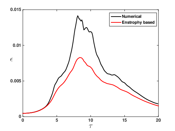
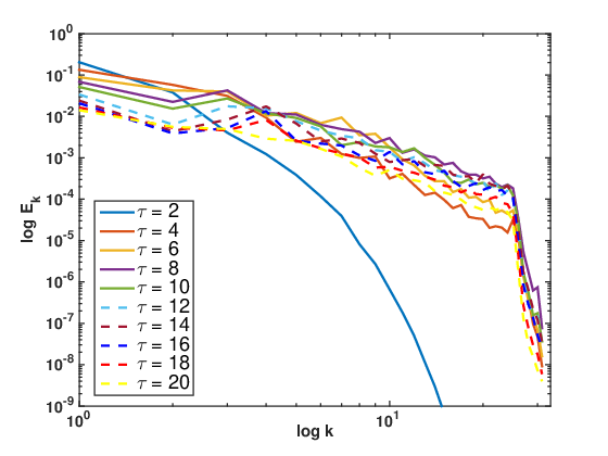
Therefore, the dissipation rate can be calculated both from the enstrophy and numerically from the evolution of the kinetic energy. From the modal energy file, it is possible to evaluate the energy spectrum of the Fourier modes. This will in turn be helpful to identify what length scales carry the most energy. After post-processing the energy files on MATLAB, you should be able to produce the following figures, which depict the time evolution of the kinetic energy and enstrophy of the flow, as well as the evolution of the dissipation rate (both computed and enstrophy-based) and the energy spectrum:
  |
The data may be plotted using the freely available gnuplot package, widely available on Linux
systems. Example gnuplot files are provided in the folders completed/solver64 and
completed/solver164. Such files can be run with the simple command:
gnuplot TGV64Energy.gnuplot
The time evolution of the kinetic energy is well predicted by the spectral, quasi-3D computation. Since no force is applied to the fluid, the initial kinetic energy in the flow is progressively dissipated, with the dissipation rate peaking at around τ ≈ 9 when the turbulent fluid structures are formed. This is consistent with the enstrophy. The enstrophy, which is a measure of how vortical the flow is, peaks at the same time as the dissipation rate, τ ≈ 9: vortex stretching increases vorticity in the stretching direction and reduces the length scale of the fluid structures. Hence, when vorticity is at its highest, the flow is dominated by these small structures, which are responsible for the main viscous dissipation effects. The discrepancy between the numerically computed and enstrophy-based dissipation rates is directly related to the resolution of the mesh. The enstrophy-based dissipation rate being lower than the numerically calculated one means that, in the simulation, not all of the dissipation is due to the vorticity present in the flow. The low resolution of the mesh accentuates the numerical diffusion present in the spectral/hp element method and is the reason for the discrepancy.
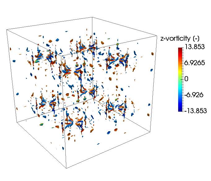
Finally, from the evolution of the energy spectrum of the Fourier modes it is possible to infer how the flow behaves. Initially, all the energy is contained in the smallest wavenumbers, meaning that the flow is dominated by the large length scales. As time passes, the energy is progressively transferred to smaller and smaller scales (larger wavenumber). This energy in the small scales peaks between τ = 8 and τ = 10, when the flow is fully turbulent, and then dies out for all wavenumbers due to dissipation. This process is depicted in the figures below, through the z-component of the vorticity.
 (a) τ=3, Laminar vortex
sheets
 (f) τ=12, Dissipation and
decay
Advanced Task: 4.2 Running the simulation with a mesh of 1283 is a bit more computationally expensive and it is left as an optional exercise. If you do run this simulation, extract the information from the energy files and plot the time evolution of the kinetic energy, enstrophy and dissipation rate for both cases under the same graphs. Establish a qualitative and quantitave comparison between the results of using different resolutions to resolve the Taylor-Green Vortex flow.
This completes the tutorial.