
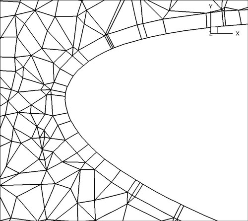
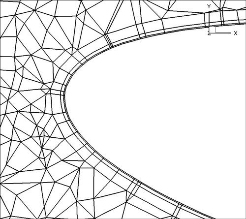
Figure 4.3: (a) Leading edge without spherigons, (b) Leading edge with spherigons
NekMesh is designed to provide a pipeline approach to mesh generation. To do this, we break
up tasks into three different types. Each task is called a module and a chain of modules
specifies the pipeline.
The figure below depicts how these might be coupled together to form a pipeline:
On the command line, we would define this as:
Process modules can also have parameters passed to them, that can take arguments, or not.
To list all available modules use the -l command line argument:
and then to see the options for a particular module, use the -p command line argument:
-p option. Input modules should be preceded
by in:, processing modules by proc: and output modules by out:.
Input and output modules use file extension names to determine the correct module to use. Not every module is capable of reading high-order information, where it exists. The table below indicates support currently implemented.
| Format | Extension | High-order | Notes |
| Gmsh | msh | ✓ | Only reads nodes, elements and physical groups (which are mapped to composites). |
| Nektar | rea | ✓ | Reads elements, fluid boundary conditions. Most curve types are unsupported: high-order information must be defined in an accompanying .hsf file. |
| Nektar++ | xml | ✓ | Fully supported. |
| PLY | ply | ✗ | Reads only the ASCII format.. |
| Semtex | sem | ✓ | Reads elements and boundary
conditions. In order
to read high-order information,
run |
| Star-CCM+ | dat | ✗ | Star outputs plt file which currently needs to be coverted to ascii using Tecplot. Reads mesh only, only support for quads and triangles (2D) and hexes, prisms, tetrahedra (3D). |
| Star-CCM+ | ccm | ✗ | Reads start ccm format. Reads mesh only, only support for quads and triangles (2D) and hexes, prisms, tetrahedra (3D). Requires NEKTAR_USE_CCM option to be activated in cmake and then requires ccmio library to be compiled by user. |
| VTK | vtk | ✗ | Experimental support. Only ASCII triangular data is supported. |
Note that you can override the module used on the command line. For example, Semtex
session files rarely have extensions. So for a session called pipe-3d we can convert this using
the syntax
Typically, mesh generators allow physical surfaces and volumes to contain many element
types; for example a cube could be constructed from a mixture of hexes and prisms. In
Nektar++, a composite can only contain a single element type. Whilst the converter will
attempt to preserve the numbering of composites from the original mesh type, sometimes a
renumbering will occur when a domain contains many element types. For example, for a
domain with the tag 150 containing quadrilaterals and triangles, the Gmsh reader will print a
notification along the lines of:
The resulting file therefore has two composites of IDs 150 and 151 respectively, containing the
triangular and quadrilateral elements of the original mesh.
The following output formats are supported:
| Format | Extension | High-order | Notes |
| Gmsh | msh | ✓ | Curvature output is highly experimental. |
| Nektar++ | xml | ✓ | Most functionality supported. |
| VTK | vtk | ✗ | Experimental. Only ASCII triangular data is supported. |
Note that for both Gmsh and VTK, it is highly likely that you will need to experiment with
the source code in order to successfully generate meshes since robustness is not
guaranteed.
The default for xml is into binary data which has been converted into base64. If you wish to
see an ascii output you need to specify the output module option uncompress by
executing:
In the rest of these subsections, we discuss the various processing modules available within
NekMesh.
To extract composite surfaces 2 and 3 from a mesh use the module extract module:
If you also wish to have the boundaries of the extracted surface detected add the detectbnd
option
To detect elements with negative Jacobian determinant, use the jac module:
To get a detailed list of elements which have negative Jacobians, one may use the list option:
and to extract the elements for the purposes of visualisation within the domain, use the
extract boolean parameter:
To turn off curvature associated with negative jacobians one can try to use the
removecurveifsingular boolean parameter:
This option will remove the high order curvature on prismatic faces with singular jacobians. This does not guarantee a non-singular mesh since it is possible for neighbouring element then to have singular jacobians. Multiple calls to the module might help with this scenario.
Where high-order information is not available (e.g. when using meshes from imaging software),
various techniques can be used to apply a smoothing to the high-order element. In NekMesh we
use spherigons, a kind of patch used in the computer graphics community used for efficiently
smoothing polygon surfaces.
Spherigons work through the use of surface normals, where in this sense ‘surface’ refers to the
underlying geometry. If we have either the exact or approximate surface normal at each given
vertex, spherigon patches approximate the edges connecting two vertices by arcs of a circle. In
NekMesh we can either approximate the surface normals from the linear elements which
connect to each vertex (this is done by default), or supply a file which gives the surface
normals.
To apply spherigon patches on two connected surfaces 11 and 12 use the following command:
If the two surfaces "11" and "12" are not connected, or connect at a sharp edge which is C0 continuous but not C1 smooth, use two separate instances of the spherigon module.
This is to avoid the approximated surface normals being incorrect at the edge.
If you have a high-resolution mesh of the surfaces 11 and 12 in ply format it can be used to
improve the normal definition of the spherigons. Run:
This can be useful, for example, when meshing the Leading edge of an airfoil. Starting from a linear mesh (left figure) the spherigon patches curve the surface elements producing leading edge closer to the underlying geometry:
When using periodic boundary conditions, the order of the elements within the boundary composite determines which element edges are periodic with the corresponding boundary composite.
To counteract this issue, NekMesh has a periodic alignment module which attempts to identify
pairs of mutually periodic edges. Given two surfaces surf1 and surf2, which for example
correspond to the physical surface IDs specified in Gmsh, and an axis which defines the
periodicity direction, the following command attempts to reorder the composites:
Here the surfaces with IDs 11 and 12 will be aligned normal to the y-axis and the surfaces 13 and 14 will be aligned normal to the z-axis.
Note that this command cannot perform magic – it assumes that any given edge or face lying on the surface is periodic with another face on the opposing surface, that there are the same number of elements on both surfaces, and the corresponding edge or face is the same size and shape but translated along the appropriate axis.
In 3D, where prismatic or tetrahedral elements are connected to one or both of the surfaces,
additional logic is needed to guarantee connectivity in the XML file. In this case we append
the orient parameter:
orient is that it throws away all high-order
information and works only on the linear element. This can be gotten around if you are just
doing e.g. spherigon patches by running this peralign module before the spherigon
module.
Often it is the case that one can generate a coarse boundary layer grid of a mesh. NekMesh has
a method for splitting prismatic and hexahedral elements into finer elements based on the
work presented in [22] and [23]. You must have a prismatic mesh that is O-type
– that is, you can modify the boundary layer without modifying the rest of the
mesh.
Given n layers, and a ratio r which defines the relative heights of elements in different layers, the method works by defining a geometric progression of points
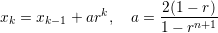
in the standard segment [−1,1]. These are then projected into the coarse elements to construct a sequence of increasingly refined elements, as depicted in figure 4.4.
To split a prism boundary layer on surface 11 into 3 layers with a growth rate of 2 and 7 integration points per element use the following command:
r=sin(x). In this case the function should be sufficiently smooth to
prevent the elements self-intersecting.
Generating accurate high-order curved geometries in Gmsh is quite challenging. This
module processes an existing linear cylindrical mesh, with axis aligned with the
z-coordinate axis, to generate accurate high-order curvature information along the
edges.
The module parameters are:
surf: Surface on which to apply curvature. This should be the outer surface of the
cylinder.
r: Radius of the cylinder.
N: Number of high-order points along each element edge.
Often one wants to visualise a particular surface of a 3D mesh. NekMesh supports extraction of
two-dimensional surfaces which can be converted using XmlToVtk or similar programs for
visualisation purposes, or combined with FieldConvert in order to extract the value of a 3D
field on a given surface.
To extract a surface use the command:
where the integers are surface IDs to be extracted.
An optional arguemnt of detectbnd can be added to identify the boundary composites as part
of the surface extraction.
The ability to remove all the high-order information in a mesh can be useful at times.
To do this in NekMesh use the command:
The output will contain only the linear mesh information, all curved information is removed.
When the mesh is three-dimensional and comprised of a prismatic boundary layer with tetrahedra in the interior of the domain, this module extracts the prismatic elements only, and constructs a boundary region for the interface between the tetrahedra and prisms. This is useful in, for example, the study of aortic flows, where the prismatic boundary layer can be extracted and refined to study unsteady advection-diffusion problems on a more refined grid inside the boundary layer.
To use this module you therefore use the command:
There are no configuration options for this module, as it is highly specific to a certain class of meshes.
Some mesh formats lack the ability to identify boundaries of the domain they discretise.
NekMesh has a rudimentary boundary identification routine for conformal meshes, which will
create a composite of edges (2D) or faces (3D) which are connected to precisely one element.
This can be done using the detect module:
This module imposes curvature on a surface given a scalar function z = f(x,y). For example, if on surface 1 we wish to apply a surface defined by a Gaussian z = exp[−(x2 + y2)] using 7 quadrature points in each direction, we may issue the command