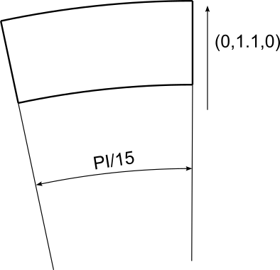
Figure 3.1: Illustration of sector rotation and base line
This section defines the movement of the mesh. Currently only static non-conformal interfaces are supported.
Non-conformal meshes are defined using ZONES and INTERFACES. Each zone is a domain as
defined in the GEOMETRY section. For a mesh to be non-conformal it must consist of
at least two zones with different domain tags. These two zones can then be split
by an interface where every interface is defined by two composite entities, we use
LEFT and RIGHT notation to distinguish between these. Each zone must contain
either the left or the right interface edge. Zones can contain multiple edges across
different interfaces but must not contain both edges for the same interface. These
left and right interface edges have to be geometrically identical but topologically
disconnected i.e. occupy the same space physically but consist of independent geometry
objects.
Non-conformal interfaces are defined enclosed in the NEKTAR tag. An example showing two
non-conformal interfaces on a single mesh is below:
1<MOVEMENT>
2    <ZONES>
3        <FIXED ID="0" DOMAIN="D[0]" />
4        <FIXED ID="1" DOMAIN="D[1]" />
5        <FIXED ID="2" DOMAIN="D[2]" />
6    </ZONES>
7    <INTERFACES>
8        <INTERFACE NAME="First">
9            <LEFT  ID="0" BOUNDARY="C[0]" />
10            <RIGHT ID="1" BOUNDARY="C[1]"  />
11        </INTERFACE>
12        <INTERFACE NAME="Second">
13            <LEFT  ID="1" BOUNDARY="C[2]" />
14            <RIGHT ID="2" BOUNDARY="C[3]"  />
15        </INTERFACE>
16    </INTERFACES>
17</MOVEMENT>
Zones must have a type specified, at the moment only ‘FIXED’ interfaces are supported
however in the future there are plans to implement rotating and sliding motion using
the ALE method. It is important for the zone IDs to correspond with the relevant
interface IDs present on the zone, that is if there is an interface with ID 0 there must
also be a zone with ID 0 too. Zone IDs must be unique but interfaces can have the
same ID, e.g. in the example above zone ID 1 has two interfaces attached to it.
The inclusion of an "INTERFACE NAME="..." allows for specifying a name, which is
used for the debug output when the verbose flag ‘-v’ is specified. This is for user
reference to ensure the non-conformal interfaces are set up correctly, and shows
zone/interface IDs, number of elements in each zone and interface, and connections
between each zone/interface. An example debug output for the above XML is shown
below:
Movement Info:
       Num zones: 3
       - 0 Fixed: 8  Quadrilaterals
       - 1 Fixed: 24 Quadrilaterals
       - 2 Fixed: 4  Quadrilaterals
       Num interfaces: 2
       - "First":  0 (4 Segments) <-> 1 (6 Segments)
       - "Second": 1 (6 Segments) <-> 2 (2 Segments)
ALE method is implemented through MOVEMENT and ALEHELPER for sliding mesh
with rotating and sliding motion. Zones type can be specified by ‘ROTATE’ and
’TRANSLATE’ interface. Recently, the ALE method is implemented in ADRSolver and
CompressibleFlowSolver.
An example for the rotationg movement is shown below:
1<MOVEMENT>
2<ZONES>
3    <FIXED ID="0" DOMAIN="D[0]" />
4    <ROTATE ID="1" DOMAIN="D[1]" ORIGIN="0,0.5,0" AXIS="0,0,1" ANGVEL="100"/>
5</ZONES>
6<INTERFACES>
7    <INTERFACE NAME="Circle">
8        <LEFT  ID="0" BOUNDARY="C[405]" />
9        <RIGHT ID="1" BOUNDARY="C[406]"  />
10    </INTERFACE>
11</INTERFACES>
12</MOVEMENT>
Here ORIGIN and AXIS are the origin and axis that the zone rotates about, respectively.
ANGVEL is the the angular velocity of rotation with radians unit.
The sector rotation can be defined using the following configuration:
1<MOVEMENT>
2<ZONES>
3    <ROTATE ID="0" DOMAIN="D[0]" ORIGIN="0,0,0" AXIS="0,0,1" ANGVEL="1" SECTOR="PI/15" BASE="0,1.1,0"/>
4    <ROTATE ID="1" DOMAIN="D[1]" ORIGIN="0,0,0" AXIS="0,0,1" ANGVEL="0"  SECTOR="PI/15" BASE="0,1.1,0"/>
5</ZONES>
6<INTERFACES>
7    <INTERFACE NAME="Sector">
8        <RIGHT ID="0" BOUNDARY="C[501]"  />
9        <LEFT  ID="1" BOUNDARY="C[502]" />
10    </INTERFACE>
11    </INTERFACES>
12</MOVEMENT>
Compared to full rotation, sector rotation applies rotational motion to only a specific portion
of the mesh, making it especially useful for simulating periodic slices of rotationally symmetric
domains, thereby reducing computational cost. Here, SECTOR specifies the angular span of the
rotating sector, in radians. For example, PI/15 defines a 12° slice. BASE defines the reference
line where the sector starts its rotation. AXIS is the axis about which the rotation occurs
(commonly the z-axis: (0,0,1)). ANGVEL sets the angular velocity (e.g., 1 for the rotating
domain, 0 for stationary).
Figure 3.1 shows a schematic of sector rotation, with the base line indicated.
To correctly apply rotational periodic boundary conditions along the sides of the sector, please refer to Section 3.4.7.3. In addition, the mesh must be pre-aligned to ensure proper periodic matching, as detailed in Section 4.5.6. Note that, current sector rotation is supported only with the Interior Penalty method for the diffusion term. Additionally, the rotation axis must coincide with one of the global Cartesian axes—x, y, or z. Rotation about an arbitrary axis is not yet supported.
Another example for the translating movement is shown below:
1<MOVEMENT>
2<ZONES>
3    <FIXED ID="0" DOMAIN="D[0]" />
4    <TRANSLATE ID="1" DOMAIN="D[1]" VELOCITY="0,PI*cos(2*PI*t)" DISPLACEMENT="0,0.5*sin(2*PI*t)"/>
5    <FIXED ID="2" DOMAIN="D[2]" />
6</ZONES>
7<INTERFACES>
8    <INTERFACE NAME="Left interface">
9        <LEFT  ID="0" BOUNDARY="C[405]" SKIPCHECK="TRUE"/>
10        <RIGHT ID="1" BOUNDARY="C[406]" SKIPCHECK="TRUE"/>
11    </INTERFACE>
12    <INTERFACE NAME="Right interface">
13        <LEFT  ID="1" BOUNDARY="C[407]" SKIPCHECK="TRUE"/>
14        <RIGHT ID="2" BOUNDARY="C[408]" SKIPCHECK="TRUE"/>
15    </INTERFACE>
16</INTERFACES>
17</MOVEMENT>
Here VELOCITY and DISPLACEMENT are the translation velocity and displacement in x,y,z
direction. SKIPCHECK is defined to ignore the missing coordinates found check for specific
interface.