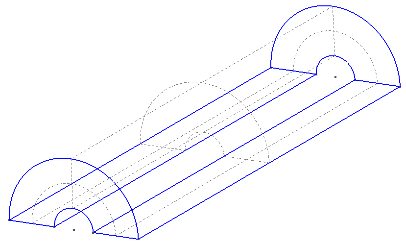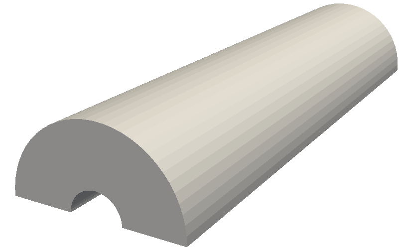


In order for us to use the mesh, we need to define the physical surfaces which correspond to
the inflow, outflow and walls so that we can set appropriate boundary conditions. The
numbering resulting from the extrusions in this case is not straightforward. In the graphical
interface, select Geometry > Physical Groups > Add > Surface, and then hover over each
of the surfaces which are shown by the dashed gray lines. The numbering will be
revealed in the toolbar underneath the geometry as a ruled surface. In this case:
Walls: surfaces 7, 8, 28, 29.
Inflow: surface 16.
Outflow: surface 24.
We also need to define the physical volumes, which can be done in a similar fashion. For this
example, there is only one volume having ID 1. Adding these groups to the end of the .geo file
is very straightforward:
1Physical Volume(0) = {1};
2Physical Surface(1)= {7,8,28,29};
3Physical Surface(2) = {16};
4Physical Surface(3) = {24};
Either choose the option File->Save Mesh or, assuming this is saved in a file named
test.geo, run the command
gmsh -3 test.geo
which will produce the resulting MSH file test.msh. One can generate a high-order mesh by
specifying the order on the command line, for example
gmsh -3 -order 6 test.geo
will generate a sixth-order mesh. Note that you will need to use a current version of Gmsh in
order to do this, most likely from subversion.